LogiCue Net System Manual
Safe use of the LogiCue Net System
- For safety and best performance of the LogiCue Net System, please follow the following safety guidelines and refer to the pictures below:
- Only use the controller with the power supply provided by the manufacturer
- Use ethernet switches that meet IEEE 802.3 standards
- Do not use near water
- Do not use with damaged cabling
- Do not attempt to repair or modify these devices. Contact us for support
- A cue light system should never be used in any scenario where safety is critical or where failure or improper operation could result in injury or property damage.
- The LogiCue Net System is an industrial product, not a toy. It contains small parts that may be harmful to children if swallowed. Keep this product away from children.
Setting up your LogiCue Net System

LCN12 Controller
The LogiCue Net LCN12 Controller comes with side panels allowing it to sit on a flat surface at a comfortable angle. The side panels can be removed for mounting in a standard 19 inch (482 mm) equipment rack. The power supply provided is a 100- 240 volt input with 1 amp 18 volts DC output with a type A input plug and a 5.5 millimeter output plug. The plug used is standard for the United States. If you would like a power supply with the correct plug for your country, notify us or let the salesperson know upon ordering.
In order to use the LCN12 Controller, the 18 volt DC power input on the back needs to be plugged in.
Next, plug an ethernet cable into the LogiCue Net output. This connector, although it is designed for Ethercon-style cables, will work with any standard ethernet cable.
Plug the other end of the ethernet cable into a port on your ethernet switch that you intend to use to distribute the signal to the cue lights.
The ethernet switch can be managed or unmanaged. If the LogiCue Net system is on its own network, unmanaged switches are fine.
The switch that the LCN12 controller is plugged into does not need to provide power over ethernet (POE) but the QLN2 cue lights do need to be plugged into a POE switch so plan your setup accordingly. The switch that the controller is plugged into can be the same switch that powers the cue lights but does not have to be. The signal can run through multiple switches without any noticeable delay.

Rear of LCN12 Controller
The rear of the LCN 12 Controller. This shows the DMX Output, the 18 volt DC input, and the LogiCue Net Output.
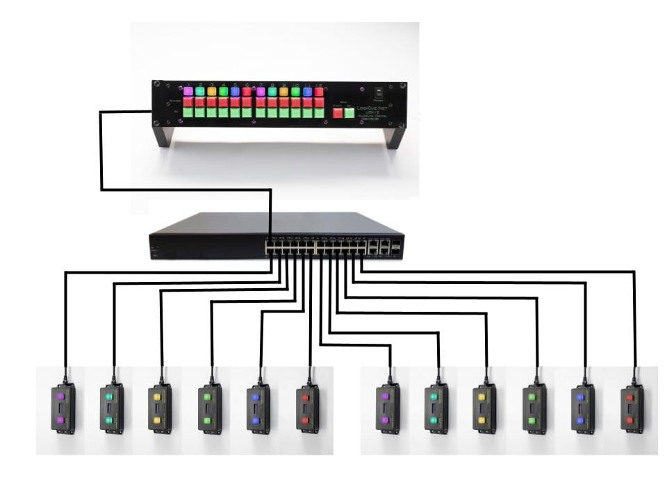
Picture 3: Wiring Diagram 1
Picture 3 shows one possible way to connect cue lights to the controller. The maximum length of the cable between the switch and the controller or the switch and the cue light is 328 feet (100 meters). For installations where greater distance is required, use multiple ethernet switches and jump them together. Fiber optic cable can be run between ethernet switches to a maximum of approximately 62 miles (100 kilometers).
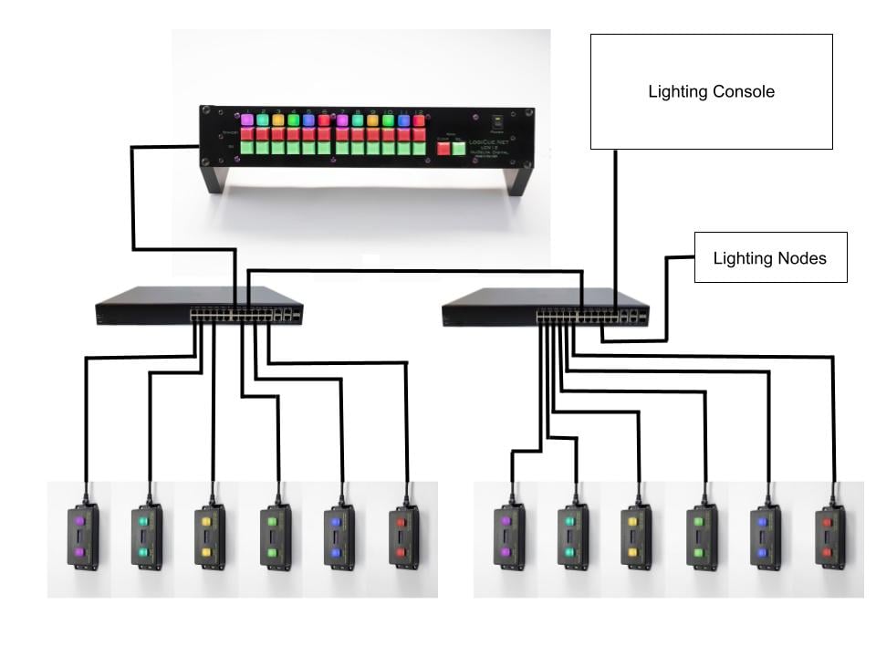
Picture 4: Wiring Diagram 2
Picture 4 shows another possible way to connect your LCN12 controller to your QLN2 cue lights using the same network switch that is used for the lighting network. This should also work on Dante audio networks, QSYS systems and other types of networked audio equipment. It may be necessary to put the LogiCue Net system on its own VLAN (Virtual Local Area Network).
.jpg)
LCN12 Controller with one QLN2 Cue Light
Operation of the LCN12 Controller and QLN2 Cue Light
If the cue lights are plugged in to a POE switch, the cue lights should display the words "Waiting for signal". This tells you that they are getting power from the POE switch. Turn the power to the LCN12 controller on by turning on the switch located in the top right corner. The green LED should light up when the controller is turned on.
It can take as much as 30 seconds for the controller and the cue lights to boot up and do their automatic check in procedure.
As the cue lights check in with the controller, the LED above each channel of the controller will light up green. This means that a cue light has checked in on that channel. The cue lights are all addressed as 1 when they are tested in the factory so all of your cue lights may be on the same address. This means that you may only see the green light illuminate above channel 1 on the controller until you have re-addressed the cue lights. How to address and change the color mode of the cue light is described below.
Once all of the cue lights have checked in, it is time to start using the controller. Pressing the red "Standby" button on one or more channels will turn the cue light on and the LED on the controller should match the color of the cue light.
Pressing the red "Standby" button twice will cause the light to flash off and on at the controller and at the cue light. If someone presses either of the two buttons on the cue light, when the cue light is flashing, the cue light will stop flashing at the cue light and at the controller. This can be used as an "acknowledge" feature so that you know an actor is in place or some other situation where a cast or crew member is not on headset.
Pressing the "Go" button of a cue light that is in a single color mode (more on that below) that is on or flashing will turn that cue light off at the controller and at the cue light.
There are six single color modes. In these single color modes, the cue light turns on in "Standby" and off in "Go" states.
Red
Blue
Green
Amber
Teal
Pink
There are also two multi-color modes:
Red/Blue/Green
Red/Blue/Off
In Red/Blue/Green mode, the cue light is red when in "Standby", green when "Go" and blue when in "Clear" mode. Clear mode is when the "Go" button has been pressed a second time or when the "Main Clear" button has been pressed. In this mode, the cue light is always in a color. The stage manager can tell the actor to go stand by the blue cue light and when it turns red, pick up their prop and get ready to enter and when it turns green, they enter.
The Red/Green/Off mode is the same as Red/Blue/Green except that the cue light is off when in the "Clear" state.
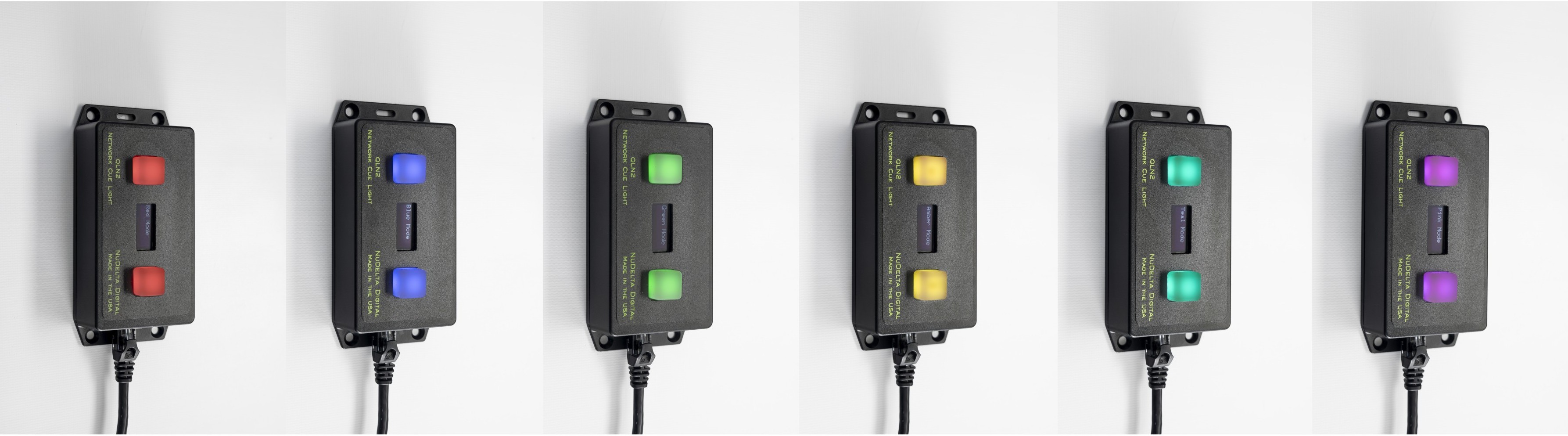
The 6 single color modes
How to Change the address on your cue lights
Each cue light can have its own address so that it can be controlled independently. The address can be changed once the cue lights are plugged in and working. When a cue light is checked in and functioning properly, there will be a check mark icon on the display of the cue light. To change the address, the channel that the cue light is currently on, needs to be in "Clear" mode. If you are not sure what the address is, just put all of the cue lights in "Clear" mode by putting all of them in "Standby", then pressing the "Main Go" button, then press the "Main Clear" button.
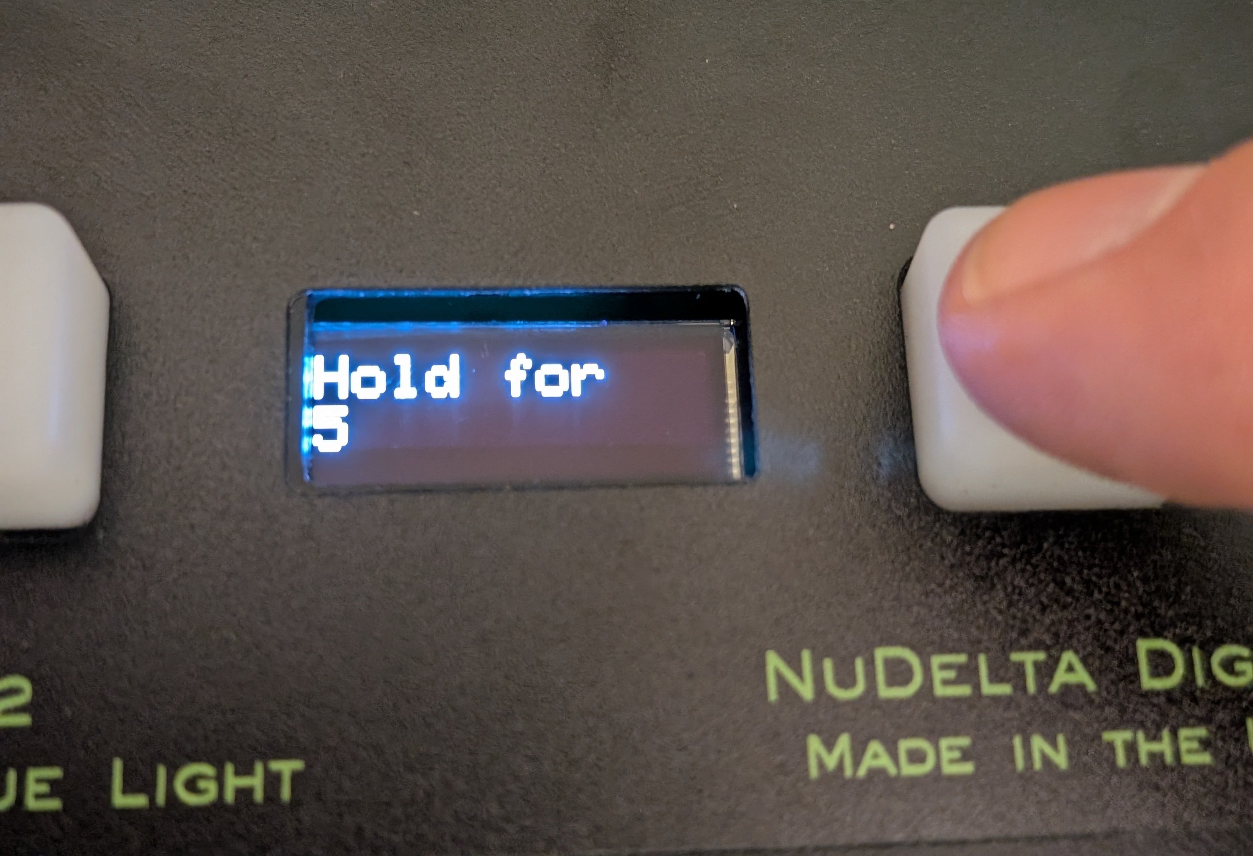
Hold right button (closest to connector) for 5 seconds
Once the cue lights are in "Clear" mode, hold the button closest to the connector until the countdown timer reaches zero and the address will appear on the screen.
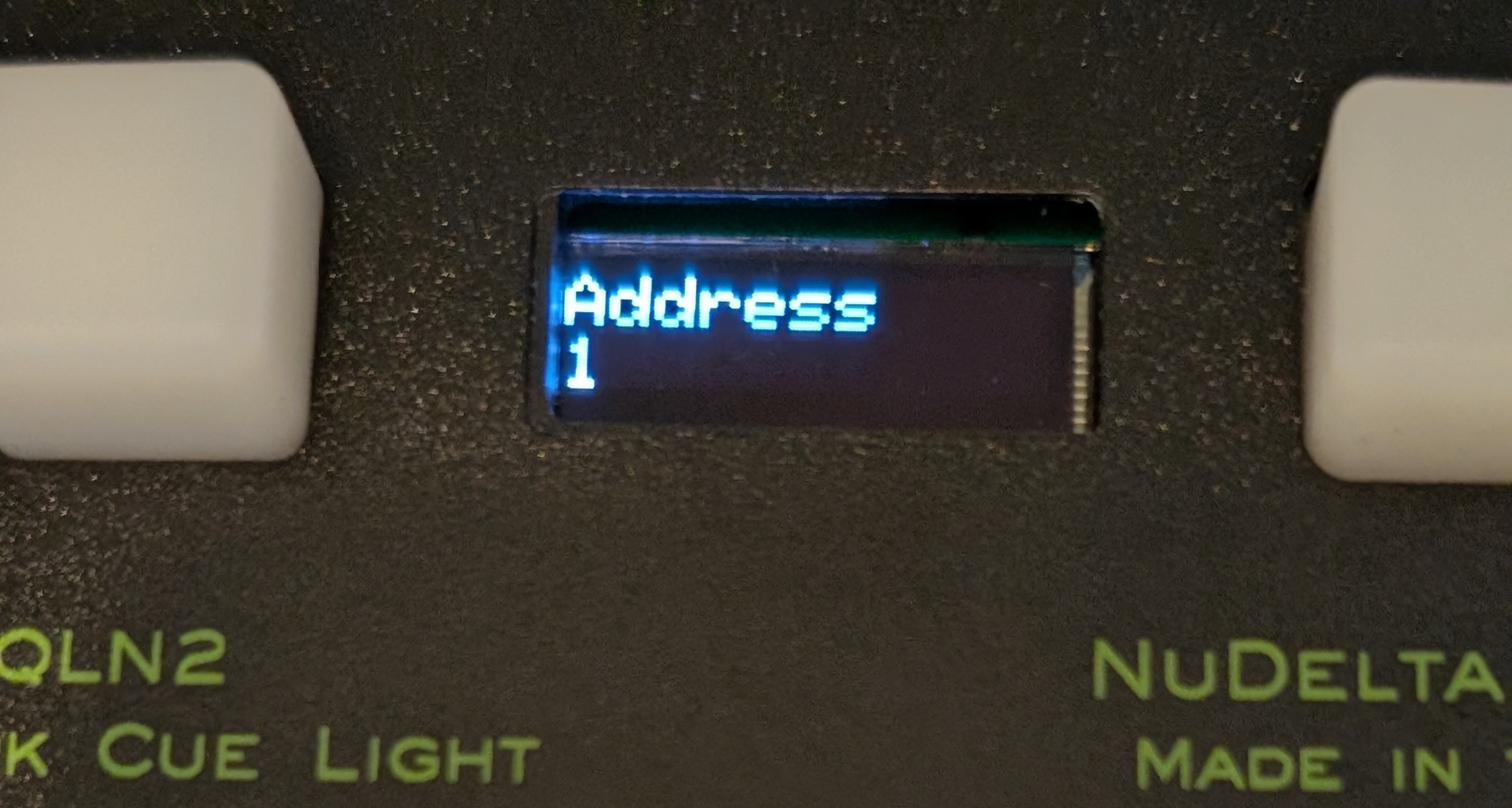
Display will show address
Once the address is shown on the screen, pressing the right button (the button closest to the connector) will advance to the next address. If you don't press the button, the cue light will record the current address and restart. Once you get to the address that you would like to use, just wait 5 seconds and the cue light will record the address and will restart. You will need to restart the controller for the controller to recognize the new address.
How to change the color mode of a cue light
As mentioned before, the cue lights have multiple color modes that they can operate in. To change color modes, unplug the cable from the cue light. Hold the button on the right (the button that is closest to the connector) while the button is held down, plug the cable into the cue light.
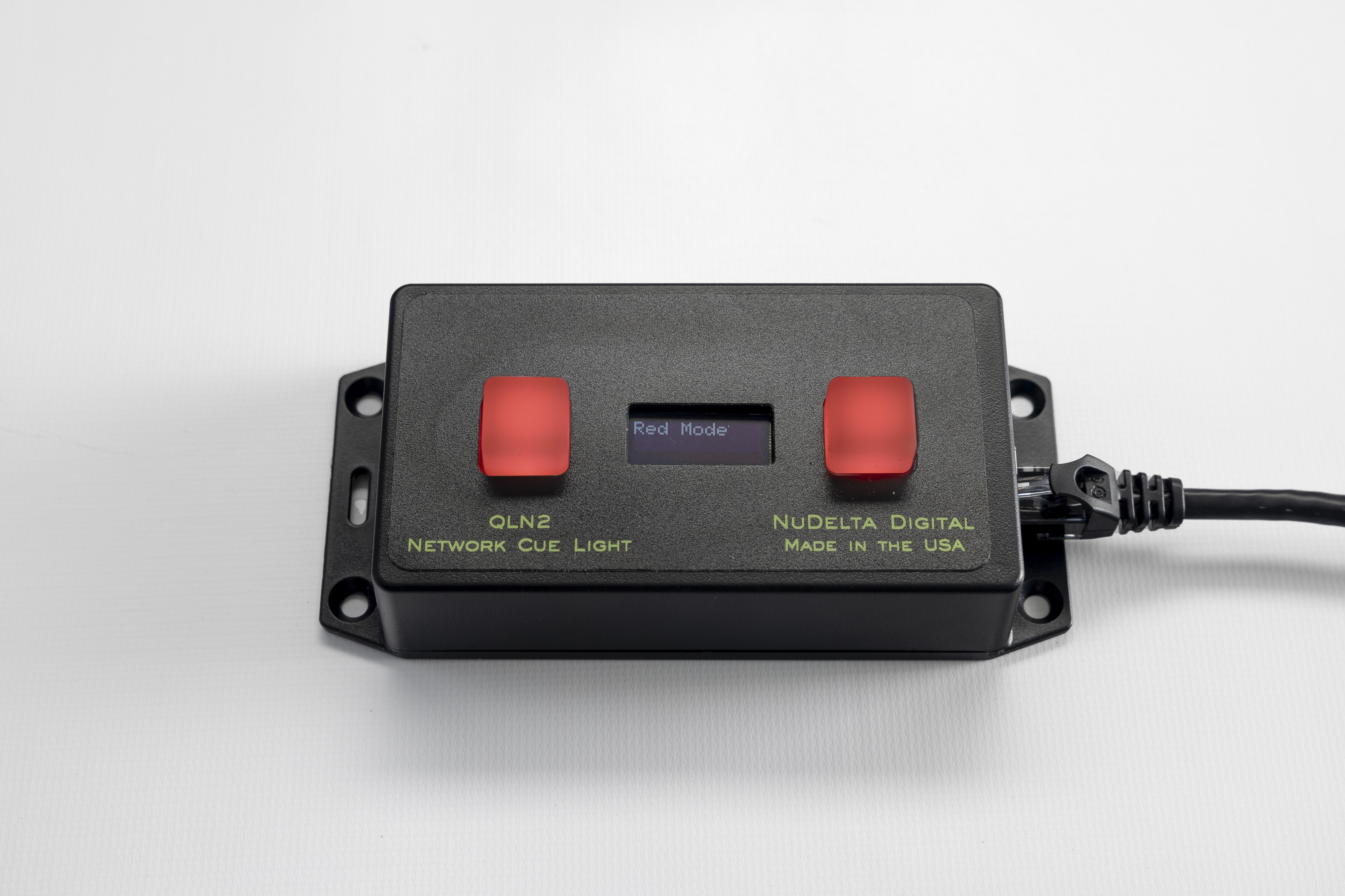
Selecting different color modes
When you plug the cable in to the cue light while holding down the button on the right, the color mode will appear on the display and the LEDs will illuminate in the color associated with that mode. Pressing the button on the right will cycle through the color modes. Once you get to the color mode that you would like to use, it is instantly recorded into the memory and you can unplug the cue light and plug it back in. You will need to restart the controller to update the color in the controller. It may be necessary to unplug and re-plug the controller in as well as restarting it by turning the power switch on the front off and back on.
Regulatory Information
1 Read these instructions.
2 Keep these instructions.
3 Heed all warnings.
4 Follow all instructions.
5 Do not use this apparatus near water.
6 Clean only with dry cloth.
7 Do not block any ventilation openings. Install inaccordance with the manufacturer’s instructions.
8 Do not install near any heat sources such asradiators, heat registers, stoves, or other apparatus(including amplifiers) that produce heat.
9 Do not defeat the safety purpose of the polarized orgrounding-type plug. A polarized plug has two bladeswith one wider than the other. A grounding type plughas two blades and a third grounding prong. The wideblade or the third prong are provided for your safety. Ifthe provided plug does not fit into your outlet, consultan electrician for replacement of the obsolete outlet.
10 Protect the power cord from being walked on orpinched particularly at plugs, conveniencereceptacles, and the point where they exit from theapparatus.11 Only use attachments/accessories specified by the manufacturer.
12 Use only with the cart, stand, tripod, bracket, or tablespecified by the manufacturer,or sold with the apparatus.When a cart is used, usecaution when moving the cart/apparatus combination toavoid injury from tip-over.
13 Unplug this apparatus during lightning storms orwhen unused for long periods of time.
14 Refer all servicing to qualified service personnel.Servicing is required when the apparatus has beendamaged in any way, such as power-supply cord orplug is damaged, liquid has been spilled or objectshave fallen into the apparatus, the apparatus hasbeen exposed to rain or moisture, does not operatenormally, or has been dropped.
15 This product is not intended for residential use. Thisproduct contains small parts that may be harmful to children